The WRight Perspective – Article Two
by Joe Bullmer
 |
| The Wright Brothers, left to right, Wilbur and Orville, at their home in Dayton, Ohio. |


As pointed out in the introduction to the first article in this series, the impressively technical Smithsonian publication The Wright Flyer, An Engineering Perspective, (hereafter referred to as the Perspective), [full text found here] has influenced the beliefs of many interested in early Wright aircraft. But the Perspective compilation includes many non-technical and some technical statements and opinions that contradict information in the Wrights’ records and in this author’s book The WRight Story.
The purpose of this series of articles is to present this author’s positions on these differences.
In addition to other material, over twelve hundred pages of the surviving records of the Wrights’ work were studied to create The WRight Story. Consequently it corrects dozens of common misconceptions concerning their work. These errors have been repeated for many decades and still are by most whose reputations have been built in part on the traditional Wright brothers’ story. The WRight Story contains hundreds of references to the Wrights’ own words and records, and detailed proofs of all points made in these discussions.
The author of The WRight Story and this series of articles has a Masters Degree in Aeronautical Engineering along with additional post graduate studies from the University of Michigan, and has worked in the field of aircraft design and performance for decades. Consequently this author is knowledgeable of the technical detail presented in the subject Smithsonian publication.
This discussion addresses the second paper in the Perspective titled Aerodynamics, Stability, and Control of the 1903 Wright Flyer. Although that section is fairly technical, effort has been made to make this discussion much less so. The length of the subject Perspective article, 20 pages of double column print, has dictated the length of this discussion. The subject article was originally an American Institute of Aeronautics & Astronomics (AIAA) Wright Flyer Project paper numbered WF 84/09-1.
The first page of the article, page 19 of the Perspective, includes the statement that by the end of 1903 “the Wrights had in hand all of the fundamental understanding and knowledge they needed to show the world how to fly”. This is a major overstatement since, as clearly shown in their writings and patent, they did not understand how cambered wings lifted their vehicle off of the ground, nor did they yet know how to control the vehicle’s direction of flight.
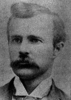 | |||||
| Edward Huffaker, important aviation provided early research and essential advice to the Wright brothers |
The next paragraph states that the Wrights “conducted the necessary tests….. to learn just what they required to succeed” giving the impression that they determined what all of these necessary tests would be. But it should be noted that they were talked into a most critical test and assisted in carrying it out by visitors to their Kitty Hawk camp, namely George Spratt and Edward Huffaker.
This test proved that the movements of the center of lift of their wings were opposite to what the Wrights had thought and exactly as Spratt and Huffaker had said, thus explaining their vehicles’ instabilities. Nonetheless, they still did not change their aircraft’s configuration. Also, both Octave Chanute and Dr. Spratt
 |
| Octave Chanute, one of the first aviation pioneers. He was the author of "Progress in Flying Machines," an early reference for all of the aviation pioneers, including the Wrights. |
familiarized them with wind tunnels, showing them photos of tunnels and the scheme for the lift-vs-drag balance that the Wrights were to use.
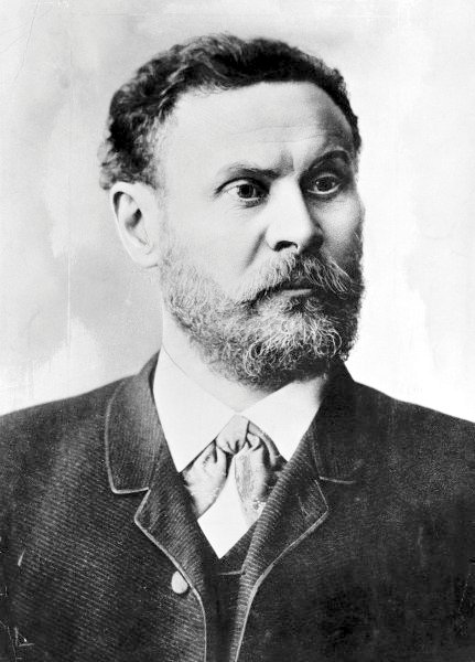 |
| Otto Lilienthal, glider pilot and great aviation pioneer. |
Page 20 of the Engineering Perspective also claims that “Otto Lilienthal had used a whirling arm apparatus to measure the lift and drag for various airfoils” clearly implying that was a likely source of errors. This is irrelevant. The data the Wrights used was developed by Otto in a natural straight steady wind. A whirling arm had nothing to do with it. This is easily proven by comparing the Lilienthal data that the Wrights used to the plates at the end of Lilienthal's book, "Birdflight as the Basis of Aviation."

The next paragraph states that “the difficulty [in generating lift] lay with "Smeaton's coefficient" This is also not true since Smeaton’s coefficient primarily affects wing area and the very successful 1902 glider had essentially the same wing area as the poorly performing 1901 machine. The reason the 1901 machine performed so badly was that both the 1901 and 1900 machines had extremely poor aspect ratios and camber shapes while the well performing 1902 vehicle did not. These were the Wrights’ own mistakes as they discovered with their wind tunnel and as they admitted in a November 24, 1901, letter to Octave Chanute.
Then on the next page the authors go on to say that “With a clever combination of their wind tunnel data and a few tests with a wing from their 1901 gliders (sic) they concluded that the correct value [of Smeaton’s coefficient] was 0.0033.” In actuality, on October 6, 1901, over a month before they built their wind tunnel, Wilbur told Chanute that "I see no good reason for using a greater [Smeaton's] coefficient than [Langley's value of] 0.0033." They had previously tried to calculate the coefficient with bicycle tests but concluded that those tests were not sufficiently accurate. So, since it seemed consistent with their glider data, they adopted Langley’s value.
On page 22 it is claimed that the great German glider pioneer Otto Lilienthal died because of “a vertical gust, or by…. raising the nose too far.” Although the Wrights had no information to dispute this, it seems extremely doubtful that, with nearly 2,000 glides under his belt, Lilienthal could have made such a novice mistake. Other more likely explanations made at the time by those familiar with his equipment include that he was of necessity practicing with a poorly maintained glider that broke a tail support, or that he was testing a new pitch control that failed.
Also on this page it is stated that “whether their aircraft were stable or unstable was an accidental matter” and so “the question of the Wrights’ intentions to design an unstable airplane is meaningless” as if they never addressed the problem, didn’t care, or their intentions can not be determined. In fact they stated quite clearly that they did care and intended to design a stable vehicle, but the movement of the center of lift with changes in angle of attack was in the opposite direction from what they thought it would be.
During his speech to the Western Society of Engineers in 1901, Wilbur stated, "Our peculiar plan of control by forward surfaces instead of tails was based on the assumption that the center of pressure would continue to move farther and farther forward as the angle [of attack] became less”. In his 1920 legal deposition Orville recalled their perplexity over the situation thus: “Our elevator was placed in front of the [wing] surfaces with the idea of producing inherent stability fore and aft, which it should have done had the travel of the center of pressure been forward [with decreasing angle of attack] as we had been led to believe. We found, however, that these machines were anything but inherently stable fore and aft.” Thus their original intentions are quite clear. They did address the problem and wanted a stable aircraft, but their basic understanding of aerodynamics was incorrect. Perpetuating the result of this mistake turned out to be extremely detrimental to the acceptance of their planes. They finally abandoned canard elevators in 1910.
Figure 3 on page 22 is incomplete, and Figure 4 on page 23 is incorrect and confusing. Figure 3 shows aircraft axes and positive rotational moments, but as a setup for Figure 4 the directions of positive angular displacements should also have been indicated.
Figure 3:

Figure 4:

Figure 4 contains three plots intended to show how stabilizing moments should vary for angular displacements along each of the aircraft’s three axes of rotation. To properly envision this problem one need first realize that the axis, angle, and moment directions are all supposed to follow what are called “right hand rules”. That means that if you take your right hand palm down and extend the thumb to the side, the first finger straight out, and the second finger straight down, then the axes of the airplane are labeled in that order. The thumb is the positive x or roll axis through the nose, the index or first finger is the positive y or pitch axis out the right wing, and the second finger is the yaw axis z positive straight down.
Then if you stick your right thumb out again and curl your fingers, as you point your thumb in the positive direction of an axis, your fingers indicate the positive direction of aircraft rotation about that axis, and the positive direction of a moment, and moment coefficient, about that axis. For example if your thumb is pointing out the nose of the aircraft your curled fingers show the direction of positive roll (right wing down) and positive rolling moment coefficient. These are standard academic conventions for the mathematics used to describe aircraft maneuvering.
A little thought reveals that, using the conventions just described, a given positive rotation of an aircraft should generate a negative torque or moment in the opposite direction to bring a stable airplane back to its original position, and visa-versa. That’s really all one needs to know. Standard graphic presentations show positive displacement angles to the right versus the moment coefficients generated plotted positive upward. Thus lines of positive stability about any axis should always have a negative slope, a positive angular displacement generating a moment in the opposite direction. The more negative the slopes, the stronger the stabilizing influences. Unfortunately, in the Perspective, Figure 4a is unnecessarily complicated, Figure 4b shows the wrong axes and slope, and Figure 4c is mislabeled.
The non-technical reader may not care about this tutorial on aircraft stability diagrams, and I would agree that it is unnecessary to a reasonable understanding of how the Wright Flyer flew. But it is instructive to see how something so seemingly impressive as Figure 4 can in fact be so confused.
Figure 5A:

Figure 5B Canard Configuration:

Figure 5A on page 24 presents four airplane stability sketches. The canard configuration shown at the top right, and shown here as Figure 5B, is claimed to be stable because the heavy positive load on the canard would cause it to stall before the wing does as the airplane pitches up, thus lowering the nose. At the limit this is indeed a stable reaction. But stability in flight is more concerned with the effects of small perturbations from nominal. In that case, as the nose of this supposedly stable canard configuration is pitched up slightly, the canard’s increased positive angle of attack would cause more pitch up. Although the main wing would develop slightly more lift, it would do so closer to the center of gravity tending to negate its stabilizing effect. Thus, unless the canard is very small, these effects would result in a further pitch up of the aircraft. This unstable pitch reaction contradicts the labeling.
The Wrights eventually reduced this problem somewhat by moving the center of gravity well forward putting a heavy positive load on the canard. (Interestingly this altered their canard configuration toward the tandem wing configuration used by Langley.)
Pages 25 through 34 display a Vortex Lattice analysis and the results of two wind tunnel investigations. Although somewhat impressive, neither contains any surprises or unexpected results, and thus they add little toward explaining the overall flight characteristics of the 1903 Flyer. The authors say as much in their summary at the end of the article.
However these pages do contain some noteworthy comments. On page 31 it is claimed that “from the beginning of their work, the Wrights chose not to use dihedral." In support of this a February, 1902, letter to Chanute is cited. However, 1902 is a long way from the beginning. In fact their first glider in 1900 began tests with dihedral in its wings, but it was later taken out leaving the wings perfectly straight. The 1901 machine also started with straight wings, but by the end of testing they had decided to arch their wings thereby using anhedral. All subsequent vehicles into 1905 used anhedral.
The article also claims that “the Wrights’ gliders had anhedral….to allow more effective use of the warp control”. It certainly made the use of a roll control more necessary, but other than making the vehicle unstable, anhedral added nothing to control effectiveness. They actually used anhedral to keep winds from blowing their vehicles back into the hillside while traversing the hill. Although dihedral would cause the wind rushing up the hillside to tilt a traversing aircraft into the hill, anhedral caused the vehicle to tilt away from the hill.
On page 31 the effect of dihedral is explained as wind blowing on the tops or bottoms of wings. This is a common explanation. However a document of the technical stature of the Perspective should point out that dihedral actually makes wings roll away from cross winds by increasing the effective angle of attack of the upwind wing and decreasing it on the down wind wing.
There is a discussion on page 32 describing the problems the Wrights had in 1904 and 1905 trying to learn how to configure and operate their vehicles to make turns. Notably, this directly contradicts the comment in the previous section of the Perspective that claims the 1902 glider was capable of making “smooth banked turns”.
Page 34 states that the “combination of warp and rudder deflection will produce….a more coordinated turn”. That is not why the Wrights connected them. They clearly stated more than once that when the aircraft inadvertently banked and they tried to right it, warping would cause it to roll, yaw and spin into the lower downward warped wing having increased drag. The original rudder was fixed straight ahead to keep the vehicle on course but this didn’t work. The rudder was then made moveable to counteract the yaw due to warping, but was only given enough deflection to keep the aircraft going straight when warping was used to correct an inadvertent roll, not enough to yaw it into, or out of, a coordinated turn. That is why the two controls had to be disconnected in 1905, to enable performing both simple roll corrections and coordinated turns.
Page 34 states that the “combination of warp and rudder deflection will produce….a more coordinated turn”. That is not why the Wrights connected them. They clearly stated more than once that when the aircraft inadvertently banked and they tried to right it, warping would cause it to roll, yaw and spin into the lower downward warped wing having increased drag. The original rudder was fixed straight ahead to keep the vehicle on course but this didn’t work. The rudder was then made moveable to counteract the yaw due to warping, but was only given enough deflection to keep the aircraft going straight when warping was used to correct an inadvertent roll, not enough to yaw it into, or out of, a coordinated turn. That is why the two controls had to be disconnected in 1905, to enable performing both simple roll corrections and coordinated turns.
Pages 35 to 41 are devoted to an extensive Root Locus analysis of the closed loop response of the aircraft to control. Much of the results of this analysis are dependent upon assumptions concerning the responses of the pilot which are represented as Kp in the diagrams. This analysis adds, little since it concludes that the vehicle can barely be controlled by a skillful and well-practiced pilot, something we already knew. However it does lead to an interesting and descriptive quantitative conclusion on page 35 stating that "stabilizing the 1903 Flyer is roughly equivalent to balancing a yardstick vertically on one's finger!"
On page 41 the argument is made that “far from abandoning warp/rudder interconnection” both wing warping and rudder movements were controlled by different movements of the same stick on later models. This is a specious argument because the original mandatory non-variable interconnection was the special feature of the Wright brothers’ control scheme that was patented. As previously mentioned, this feature had to be abandoned in 1905, a year before the patent for it was issued, in order to make turns. Although this feature had been abandoned, it was vigorously defended by the Wrights in subsequent patent infringement battles.
The next article in this series will discuss the longitudinal dynamics of early Wright Flyers.
* Marvin MacFarland's "The Papers of Orville and Wilbur Wright" are fully digitized at hathiway trust.org. The link is to Volume I of two volumes.
_________________________________________________________

Joe Bullmer, above, has a Master's degree plus advanced studies in Aeronautical Engineering. His first contribution to the"Truth in Aviation History"series of articles is "Joe Bullmer Rebuttal to Tom Crouch in the"Huffington Post."
All of the pictures and most of the links in this essay were selected and added by the founding editor of "Truth in Aviation History."__
* Marvin MacFarland's "The Papers of Orville and Wilbur Wright" are fully digitized at hathiway trust.org. The link is to Volume I of two volumes.
_________________________________________________________

All of the pictures and most of the links in this essay were selected and added by the founding editor of "Truth in Aviation History."__
1 comment:
The reality creator of the airplane was the Brazilian Alberto Santos Dumont. Wright's machine could not take off by its own means. Always needed the help of strong winds, gravity or a catapult to take off. Dumont was the first in 1906 to take off by its own means.
Post a Comment